
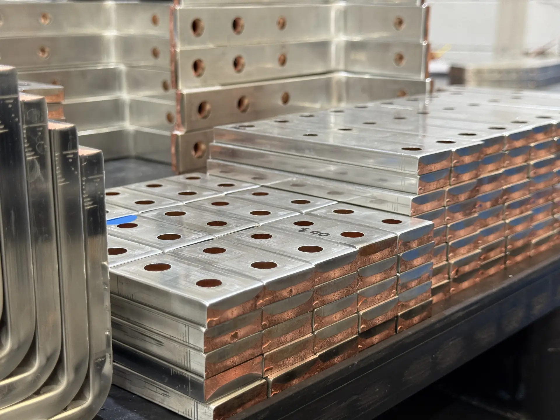
A busbar drawing should clearly specify the conductor material, dimensions, hole positions, bends, tolerances, surface finishes and relevant electrical requirements.
Providing this information upfront helps manufacturers assess production requirements, identify potential issues and prepare accurate quotations with fewer clarification requests.
Whether you are specifying copper busbars for switchgear, developing a power distribution system or sourcing replacement components, a well-prepared engineering drawing is essential for efficient manufacture.
ILF Products supplies and manufactures custom copper and aluminium busbars from its facility in Cannock, Staffordshire.
This practical guide explains what engineers, manufacturers and procurement teams should include when preparing a busbar manufacturing enquiry.
Why Does a Detailed Busbar Drawing Matter?
A technical drawing communicates how a busbar should be manufactured, including its geometry, material specification and critical dimensions.
Missing or ambiguous information can lead to unnecessary correspondence, manufacturing assumptions and potential discrepancies between the intended design and finished component.
For manufacturers, a clearly dimensioned drawing provides the information needed to:
- Determine material requirements and suitable stock sizes.
- Plan cutting, punching, bending and CNC machining operations.
- Assess manufacturing feasibility and tooling requirements.
- Confirm critical tolerances and inspection requirements.
- Identify processes that may affect production costs.
For repeat orders, an approved drawing also provides a consistent manufacturing reference, helping ensure components meet the same specification across production batches.
What Should You Include on a Busbar Drawing?
1. Material Grade and Busbar Dimensions
Start with what the bar is made of and how big it is.
Your drawing should include:
- Material: Copper or aluminium.
- Material grade: For example, C101 (CW004A) high-conductivity copper, or the aluminium alloy and temper, such as 6101 or 6082-T6.
- Thickness: The specified material thickness is in millimetres.
- Width: The required conductor width.
- Length: The finished overall length, plus the developed (flat) length if the bar is bent.
Quantity of identical parts.
Copper carries more current for a given cross-section, which is why it dominates compact switchgear. Aluminium is lighter and often cheaper per bar, though you’ll usually need a larger section and a different approach to the joints. If you’re weighing the two up, our guide on when aluminium is the right choice for a busbar goes into more detail.
Grade matters as much as material. Different copper and aluminium alloys bend, machine and conduct differently, so please name the grade your design was approved against rather than leaving it as “copper”. If we think another grade would serve you better, we’ll say so before proceeding.
2. Hole Positions, Bends and Tolerances
This is where most of the detail lives, and where a missing dimension costs the most time.
Your drawing should show:
- Hole diameters, centres and pitch.
- Slots, cut-outs and distances from edges.
- Bend angles, positions and direction.
- The internal bend radius you need.
- Finished dimensions after bending, not just the flat blank.
The tolerances that genuinely matter for fit.
On bend radius: it’s the inside radius of the bend, and what’s achievable depends on the grade, thickness, temper, bend orientation and tooling. If your design needs a tight radius, tell us early so we can confirm it before quoting.
Our EHRT bending machines hold bend angles to ±0.1° on bars up to 2000 mm long, and handle offsets, flat bends, torsion bends, U-bends and closed shapes, so complex geometry is rarely a problem as long as it’s clearly drawn.
For bars with several bends, show the sequence or add an isometric view so there’s no doubt about the finished shape. Use datums for anything that has to line up with a terminal or mounting face.
A word on tolerances: tight ones only where the function needs them. A ±0.1 mm tolerance on a clearance hole for an M12 bolt adds cost and inspection time without making the bar fit any better.
3. Plating, Insulation and Surface Finish
Finish affects contact resistance, corrosion protection and how the bar installs, so spell it out rather than leaving it to the quote stage.
Depending on the job, specify:
- Tin, nickel or silver plating, which we arrange through our plating partners.
- Full or selective plating, with any contact faces that must stay bare clearly marked.
- Required coating thickness.
- Deburring, linishing or edge radiusing.
- Insulation sleeving or protective coating.
Which plating suits your job depends on the mating material, the environment and the electrical spec. Tin is the common choice for general protection and for joints to aluminium.
Silver is used where the lowest contact resistance matters. Nickel suits high temperatures or corrosive environments. If plating thickness affects a critical dimension, note on the drawing whether the dimension applies before or after plating.
What Electrical Details Should go with the Drawing?
The drawing defines the part. The electrical duty tells us whether the part makes sense, and it helps us flag anything that looks marginal before it’s made.
Where you can, include:
- Current rating: continuous current and any short-circuit withstand requirement.
- Operating voltage and insulation requirements.
- Installation environment: ambient temperature, ventilation and enclosure type.
- Clearances to other live parts and earthed metalwork.
- Applicable standards and project specifications.
Busbar sizing is about more than cross-section. Conductivity, heat dissipation, joint resistance, and how the bars are arranged and the temperature they’ll run at all play a part.
Our guide to copper busbar sizing covers the main factors. For low-voltage switchgear and control gear assemblies, the BS EN IEC 61439 series is usually the relevant standard.
One important caveat: sizing, safety and compliance stay with your qualified design engineer. We manufacture to your approved design, and a quote from us isn’t a substitute for the electrical calculations behind it.
What Else do we Need to Quote Accurately?
Alongside the drawing, a few commercial details help us give you a firm price rather than a budget figure.
- Quantity: The number of components required for each drawing.
- Samples or prototypes: we can make sample busbars for you to check before the full run.
- Schedule: a one-off, or a repeat order you expect to call off over time.
- Delivery: required dates and where the parts are going.
- Documentation: material certificates or inspection records, if your project needs them. We’re certified to ISO 9001, so this is routine for us.
- Future demand: likely annual volumes, if you know them.
Quantity and complexity decide how we make the part. A repeating hole pattern across a batch suits our punching line.
Intricate features or tight tolerances usually mean CNC machining. Knowing your likely demand also lets us hold the right stock for you, which is often the difference between a short lead time and a long one.
Which File Formats Should You Send for a Busbar Quote?
A dimensioned PDF is the ideal starting point. CAD files alongside it help us check the geometry and program the machines.
Commonly used formats include:
- PDF: the approved drawing with dimensions, tolerances and notes.
- DXF: 2D profiles, hole layouts and cut-outs.
- DWG: full engineering drawings.
- STEP: 3D geometry for complex parts.
- Sketches or photos: fine for an early-stage enquiry.
Our online drawing upload accepts PDF, DXF, DWG, JPG, PNG and GIF files up to 5 MB each.
For STEP files or anything larger, email them to sales@ilfproducts.co.uk, and we’ll pick them up from there. Whatever you send, make sure every file is the same revision.
Common Busbar Drawing Mistakes that Slow Down a Quote?
A detailed drawing can still hold up a quote if its dimensions, references or notes disagree with each other. These are the issues worth a second look before you press send.
Mixed revisions: A new CAD file sent with an old PDF leaves us guessing which one to build to. Put the revision in the title block of every file and check that they match.
Floating dimensions: Dimensions taken from different reference points make hole positions and bend locations hard to pin down. Use consistent datums and flag the critical mounting dimensions.
Flat versus finished: A bent busbar’s developed length isn’t the same as its finished length. Make clear which one you’ve dimensioned, and ideally show both.
Bend direction left to the imagination: A 90° bend can go four ways. An isometric view or an extra projection removes the doubt.
Schedules that don’t add up: On multi-bar assemblies, check that the drawing numbers, quantities and specifications match the bill of materials.
Ten minutes spent on these before you send the enquiry saves a lot of emails afterwards.
Busbar Drawing Checklist
Run through this before you send your next enquiry:
- Material and grade named, not just “copper” or “aluminium”.
- Thickness, width and finished length given.
- Holes, slots and connection centres dimensioned from clear datums.
- Bend angles, directions and internal radii shown.
- Critical tolerances stated, and only where needed.
- Plating, insulation and finish specified, including bare contact areas.
- Current, voltage and applicable standards noted.
- All files at the same revision, with CAD attached where available.
- Quantity, documentation and delivery requirements included.
Send us your Busbar Drawing
Whether it’s a fully toleranced drawing package or a sketch on the back of an envelope, we’d like to see it.
Upload it through the drawing form on our busbar design page, email sales@ilfproducts.co.uk, or call 01543 226816 and talk it through with the team in Cannock. You can also reach us through our contact page.
Milly Edwards

Sales and Marketing Executive: Responsible for creating content for ILF's social media channels, website, print media and promotional work.